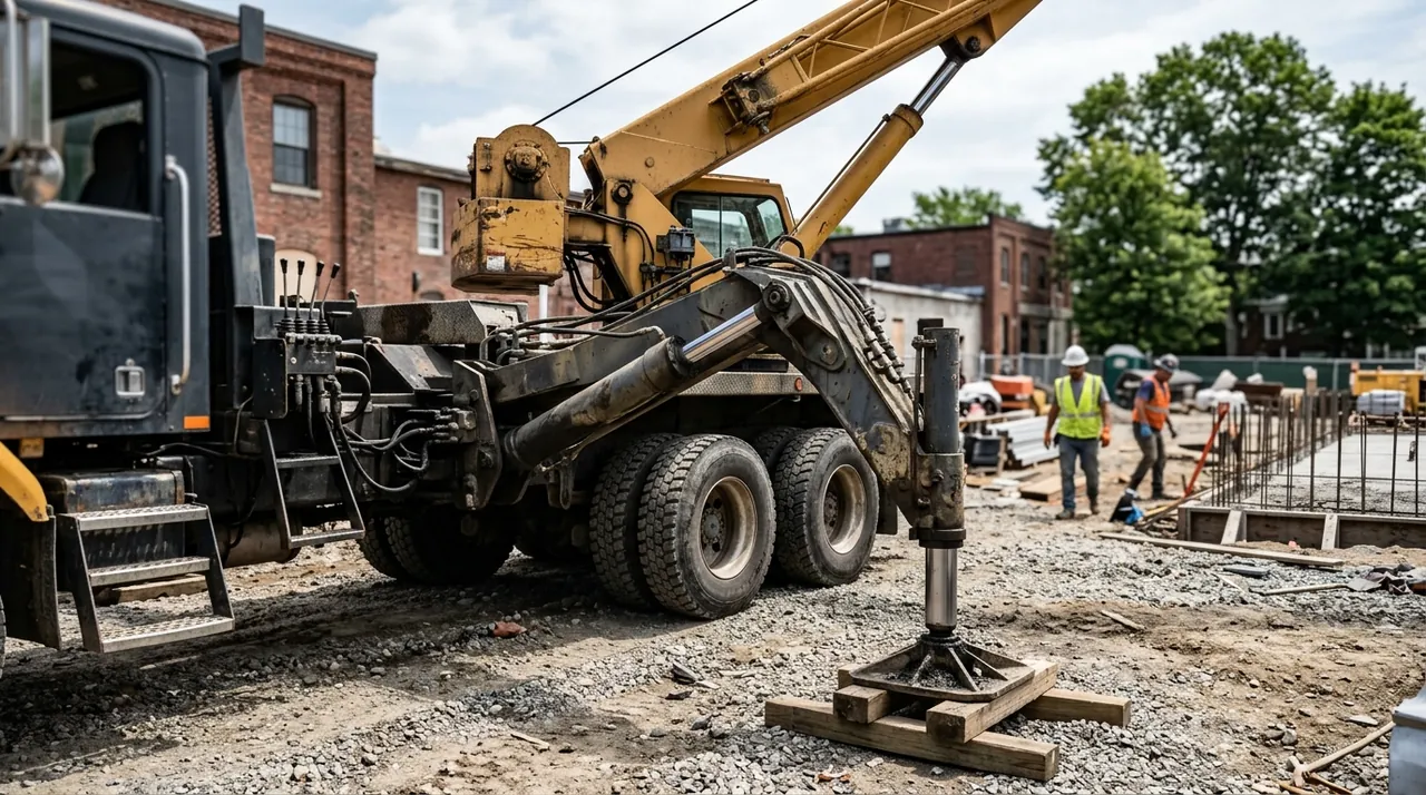
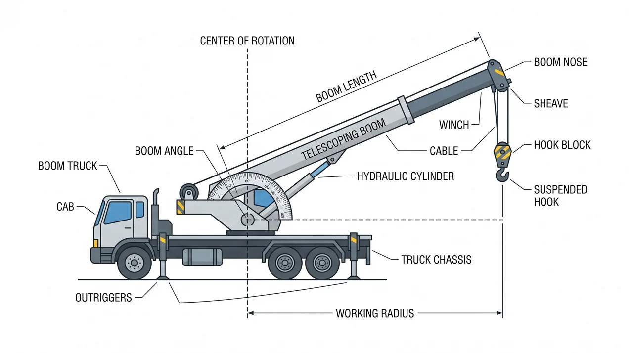
Before you can read a load chart or set an outrigger, you need to know what you are sitting in. A hydraulic boom crane looks simple from the outside — a truck with a big arm — but every component has a specific job in the load path. This session walks the machine from the ground up: carrier, rotating upper, telescoping sections, the knuckle on an articulating crane, and the geometry that ties boom angle and boom length to the number that controls every lift — the working radius.
Carrier and upper: two machines in one
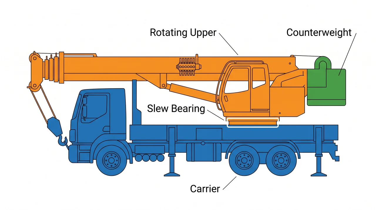
Every truck-mounted boom crane is two machines sharing a frame. The bottom half is the carrier — the truck chassis that gets the machine to the job site and provides the mass and footprint that keep it stable once you are set up. The top half is the rotating upper, which holds the boom, hydraulic valve bank, and operator controls. These two halves connect through the slew bearing and hydraulic swing drive, letting the upper rotate through its full swing arc — 360 degrees on many machines, though some designs allow only limited-arc rotation.
The carrier's weight and any counterweight mounted on the upper both contribute to stability. Counterweight shifts the center of gravity toward the rear so the machine can carry greater loads over the front and sides without tipping. Never remove or substitute counterweight sections without verifying the configuration matches the load chart in use.
On a 1C machine there is no separate wire-rope hoist drum like you find on a 1B truck crane. The load-handling device — hook, grapple, or fork — attaches directly to the boom nose, and all lifting force comes from hydraulic cylinders. That distinction is exactly why 1C machines carry their own license restriction.
Telescoping boom: base section, fly sections, and extension cylinders
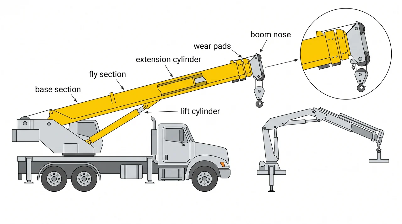
The telescoping boom starts with a base section pinned to the boom pivot on the upper. Inside sit one or more fly sections — nested tubes that slide in and out along wear pads. Wear pads are low-friction blocks that keep the sections aligned; a worn pad lets the sections cock sideways and concentrate stress on the boom walls, so inspect them regularly.
Boom extension is powered by an internal extension cylinder or a wire-rope extend system — but this rope moves the boom sections, it does not hoist the load. All lifting force comes from the lift cylinder that raises and lowers the boom angle. At the far end of the outermost fly section sits the boom nose with its sheaves or the attachment mounting point. Any damage there — bent sheave pins, cracked nose casting — is an immediate removal-from-service condition.
Articulating booms and the knuckle joint
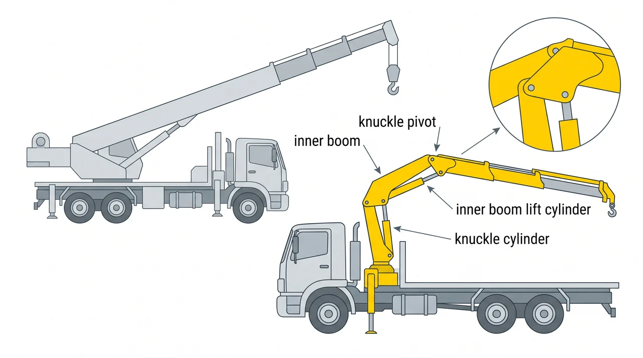
An articulating (knuckle-boom) crane divides the arm into two segments. A lift cylinder raises and lowers the inner boom, just like a telescoping crane. A second cylinder opens and closes the outer boom at the knuckle pivot, letting it fold back over the machine for travel or reach into tight spaces a straight boom cannot access. Common attachments include grapples, pipe hooks, and hydraulic forks — reflecting how widely these machines are used in delivery and utility work.
Working radius and why it controls capacity
Working radius is the horizontal distance from the center of rotation to the suspended load. Every rated capacity on the load chart is tied directly to it. Extend the boom sections outward or lower the boom angle — either move the load farther from the center of rotation, increasing the radius and decreasing the rated capacity. The crane is a lever, and moving the load farther from the fulcrum increases the overturning moment.
Before any lift, you must know your boom length, your boom angle, and therefore your working radius. Then consult the load chart for that exact radius and configuration. Getting any one of those inputs wrong means the chart number you read does not apply to your setup.
Key Takeaways
- •A 1C crane is a carrier and a rotating upper joined by a slew bearing — the upper rotates through its full swing arc (360° or limited); all lifting force comes from hydraulic cylinders, not a wire-rope hoist drum.
- •Carrier mass and counterweight both contribute to stability — never remove or substitute counterweight without verifying it matches the load chart configuration.
- •The telescoping boom extends via internal cylinders; wear pads keep sections aligned and must be inspected for wear.
- •On a knuckle-boom, a second cylinder folds the outer boom at the knuckle joint, enabling reach into tight spaces and compact travel dimensions.
- •Working radius is the horizontal distance from the center of rotation to the load — a longer boom or lower angle both increase radius and reduce rated capacity.
- •Every lift requires knowing boom length, angle, and working radius before reading the load chart — a wrong input means the chart value does not apply.