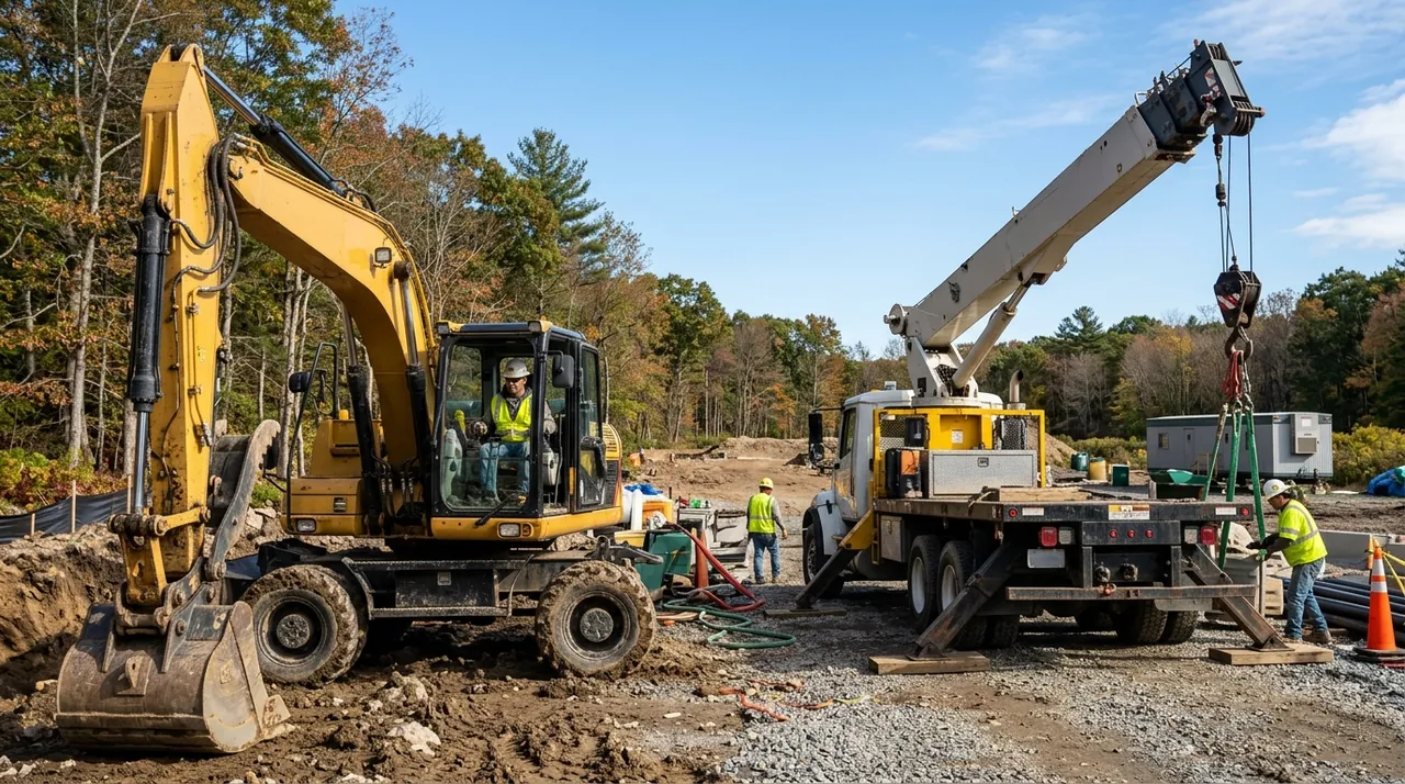
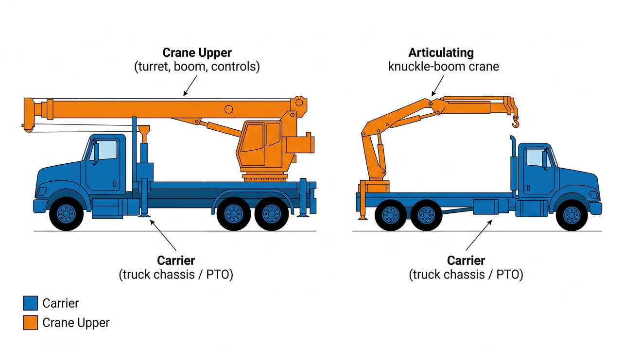
A hydraulic boom truck is two machines sharing one chassis: a carrier that drives the work site and a crane upper that does the lifting. Before you can operate one safely — or answer the 1C questions on the Massachusetts exam — you need to name every major assembly, explain what it does, and understand how the pieces interact to create or destroy a stable lift. This session builds that mental map.
Carrier and crane upper: the two-assembly foundation
The carrier is the truck chassis — engine, drive axles, cab, and frame. It moves the machine between jobs and provides the power take-off (PTO) that drives the hydraulic pump. Everything that lifts is mounted on the crane upper, sometimes called the turret or pedestal. The turret sits on a slewing ring and can rotate — slew — to swing the boom in any direction relative to the truck.
This two-part distinction matters on the job and on the exam. The carrier has its own rated capacities for road speed and axle loads. The crane upper has separate rated lifting capacities. A truck legal on the highway can still be in an unstable lift configuration once the boom is deployed.
Telescoping versus articulating booms — and why 1C has no hoist line
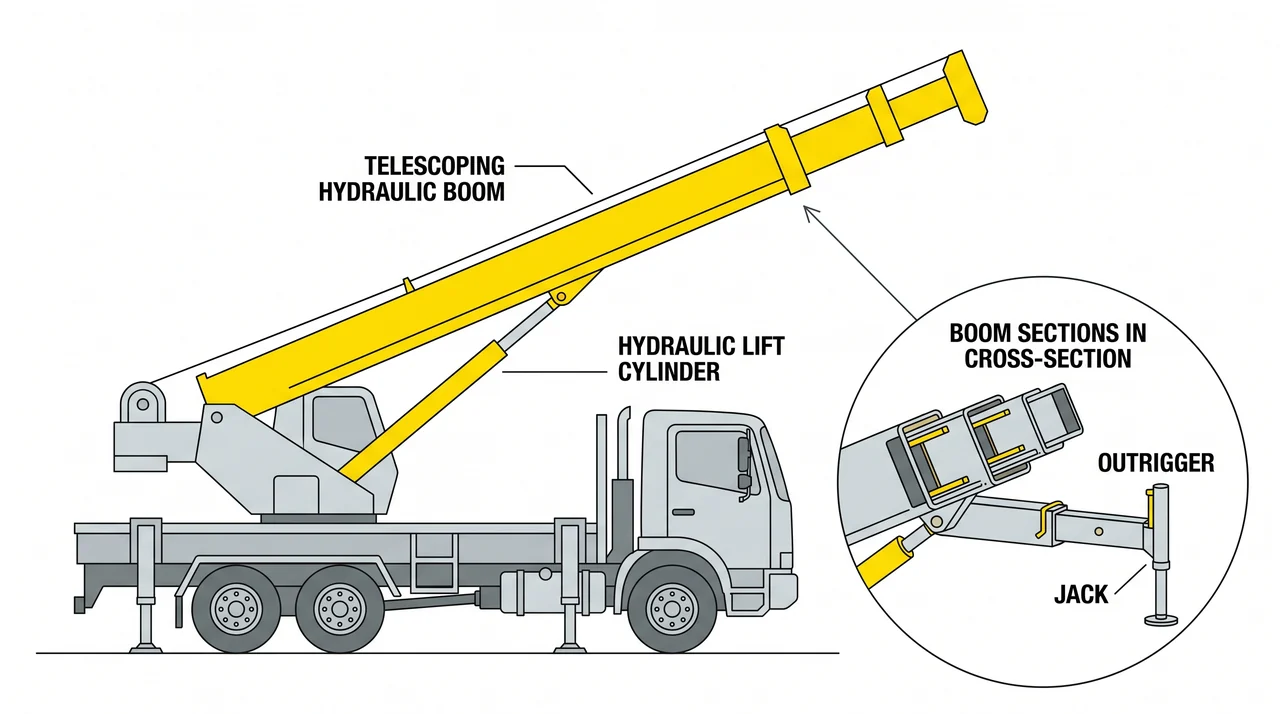
A telescoping boom is a series of nested steel sections that slide in and out, powered by internal hydraulic cylinders. Extending the sections increases reach; retracting them shortens it. The boom pivots at its base to raise and lower.
An articulating boom — the knuckle-boom — uses hinged sections instead of sliding ones. The inner boom pivots at the turret, and the outer boom pivots at the knuckle joint between them. Folding and unfolding those joints hydraulically lets the operator position a load that a straight boom could not reach without moving the truck.
On both types, the 1C machine lifts with the boom itself — there is no wire rope, no winch drum, no hoist line. The load-handling device rides at the boom tip; common attachments include a hook block, a grapple, forks, or a brick/block clamp depending on the job. The hydraulic cylinders do all the work of raising and positioning. Add a winch and a wire-rope hoist line to a telescoping-boom truck and the machine becomes a 1B crane. That dividing line is tested directly on the Massachusetts exam.
Outriggers, stabilizers, and ground support
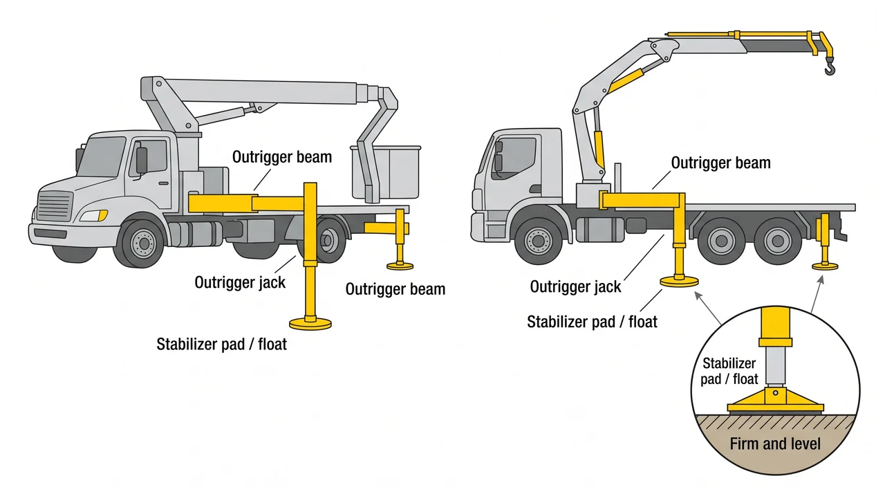
A boom truck in driving configuration has a narrow wheel base. Deploy the boom off to the side and the tipping moment can overwhelm the truck's tire footprint in seconds. Outriggers solve this by extending horizontal beams from the frame — widening the support base — and then driving vertical jacks down to the ground to take weight off the tires entirely.
At the base of each jack sits a stabilizer pad or float, a wide plate that spreads the point load over a larger ground area. The condition of those pads and, more critically, the firmness and levelness of the ground under each one, directly determines how much of the rated capacity chart you can safely use. Soft, wet, or sloped ground under an outrigger is one of the most common causes of boom-truck tipping incidents. Before any lift, verify that all outriggers are fully extended per the load chart configuration, pads are fully in contact with firm ground, and the machine is level.
Hydraulic system and overload protection
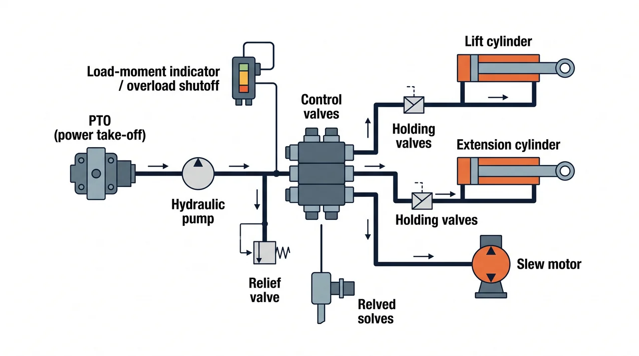
The PTO drives a hydraulic pump; control valves direct flow to each cylinder or motor; relief valves vent excess pressure to protect hoses and fittings. Holding valves on the lift and extension cylinders trap oil when controls are at neutral, preventing the boom from drifting down under load.
Many machines also carry a load-moment indicator or automatic overload shutoff. As the boom lengthens or lowers, the same load weight creates a larger tipping moment, and these systems limit or stop movement before the rated limit is exceeded. They are a backup safety device, not a replacement for the load chart. The capacity plate and chart are mounted on the machine and are your primary reference — rated capacity changes with boom length, angle, and outrigger position.
Key Takeaways
- •A boom truck is a carrier (truck chassis and PTO) plus a crane upper (turret, boom, and controls) — each has its own rated limits.
- •A 1C machine lifts with the hydraulic boom itself — no wire rope or winch. The boom-tip load-handling device (hook, grapple, forks, or clamp) is powered by the same hydraulic circuit. A winch-and-rope telescoping boom truck is a 1B machine.
- •Telescoping booms extend and retract for reach; articulating (knuckle) booms use hinged sections to position loads around obstacles.
- •Outriggers widen the support footprint and must be fully extended on firm, level ground before any lift — ground conditions directly affect rated capacity.
- •Always read the on-machine load chart for each configuration; load-moment indicators are a backup safety device, not a replacement for the chart.