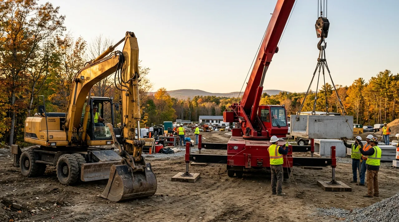
The hydraulic boom truck looks simple from the ground — a truck with a folding arm and a hook. But the moment you attach a load, you are working inside a precise mechanical relationship between radius, angle, boom length, and ground stability that gravity will enforce without warning. Most tip-overs happen on routine lifts because operators skip steps they have done a hundred times before. This session covers what your exam will test and your job will demand: reading the chart correctly, setting up the machine completely, and recognizing the conditions that push a lift toward failure.
Reading the Load Chart: Radius, Angle, and Boom Length
The load chart is the legal and physical limit of what your machine can lift in any given configuration. Every row and column corresponds to a specific combination of boom length, boom angle, and load radius. Load radius — the horizontal distance from the center of rotation to the hook — is the dominant variable. As radius increases, the effective moment arm on the machine grows, and rated capacity drops, often sharply. Swing the load out two feet and you may shed hundreds of pounds of capacity.
Boom angle and boom length compound the effect. Extending the boom at a shallower angle both increases radius and lengthens the structural moment arm, pushing capacity down further. You must read the chart at the actual configuration you are working in. If your radius or boom position falls between chart values, use the more conservative (lower) figure.
Before using any chart number, deduct the weight of everything hanging below the boom tip: hook block, rigging hardware, slings, shackles, and any auxiliary attachment. What remains is the net capacity — the actual limit for the load. The exam will test whether you know this distinction.
Outrigger Setup and Ground Bearing
Outriggers widen the tipping base beyond the truck's narrow wheel track. They only do that job when fully extended to the width the load chart assumes — partial extension reduces rated capacity and moves the tipping fulcrum inward. Extend them fully, deploy the pads or floats, level the machine, and lift the tires clear so suspension flex cannot shift the load during the pick.
The ground under each pad carries the full combined weight of the truck and load, concentrated into a small contact area. Soft soil, recently backfilled trenches, frost-weakened ground, and summer asphalt can all punch through under that load. When the surface is questionable, crib under the pads with timber mats or blocking to spread the load. That step is not optional on suspect ground — it is what keeps the outrigger from sinking and rolling the machine.
What Causes Tip-Overs and How to Prevent Them
The three leading causes of boom-truck tip-overs are over-radius lifts, partial outrigger extension, and soft or failing ground — and they often combine. An over-radius lift happens when an operator estimates the radius rather than measuring it, or booms out to clear an obstacle without rechecking the chart. The machine gives no graduated warning as it approaches the tipping point.
Dynamic loads compound the risk. Dragging a load sideways, picking from a sling that is not plumb, or hoisting with a jerk generates forces that exceed the static chart value. The chart assumes a smooth, vertical, controlled lift — side-loading or shock loading can exceed capacity even when the static number looks safe.
Knuckle-boom cranes add complexity because the articulated joint changes the effective radius continuously through the lift. Capacity changes at every position of that joint, and you must track the chart throughout the lift — not just at the start.
Overload Indicators and Regulatory Standards
Load-moment indicators and overload shutoff systems signal when you are at or past the chart limit. When a shutoff activates during a lift, stop all movement, assess the configuration, and set the load down in the safest available direction. Bypassing or overriding the system to finish the lift is a serious violation — these are hard limits, not advisory warnings.
OSHA 29 CFR 1926 Subpart CC governs crane and derrick operations on construction sites, covering operator qualification, inspection, and lift planning. ASME B30.5 applies to mobile cranes and ASME B30.22 to articulating boom cranes; both set safe-practice standards the industry follows. Subpart CC also requires maintaining required clearance from energized overhead power lines during every lift — that requirement applies to the most routine pick on the busiest morning.
Key Takeaways
- •Load radius is the dominant factor in rated capacity — as radius increases, capacity drops; always read the chart at your actual configuration, never interpolate upward.
- •Deduct the weight of the hook, rigging, and all attachments from the chart value to get the net capacity available for the actual load.
- •Outriggers must be fully extended to the chart-assumed width, pads leveled, and tires lifted before any lift — partial extension invalidates the chart.
- •Soft, frozen, or backfilled ground can fail under concentrated outrigger loads; crib and pad as needed to spread the load.
- •The three leading tip-over causes are over-radius lifts, partial outrigger extension, and bad ground — and an overload shutoff must never be bypassed.