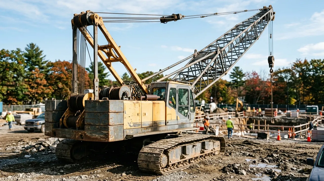
Before you can safely operate a lattice-boom crawler crane, you have to picture it as a system — not a pile of steel parts, but a machine where every component has a defined job that depends on the others doing theirs. The MA 1A exam will ask you to identify components by name and explain what they do. More importantly, the job demands that you recognize a problem when you see one, and you can only do that if you already know what normal looks like. This session walks through crawler crane anatomy from the ground up.
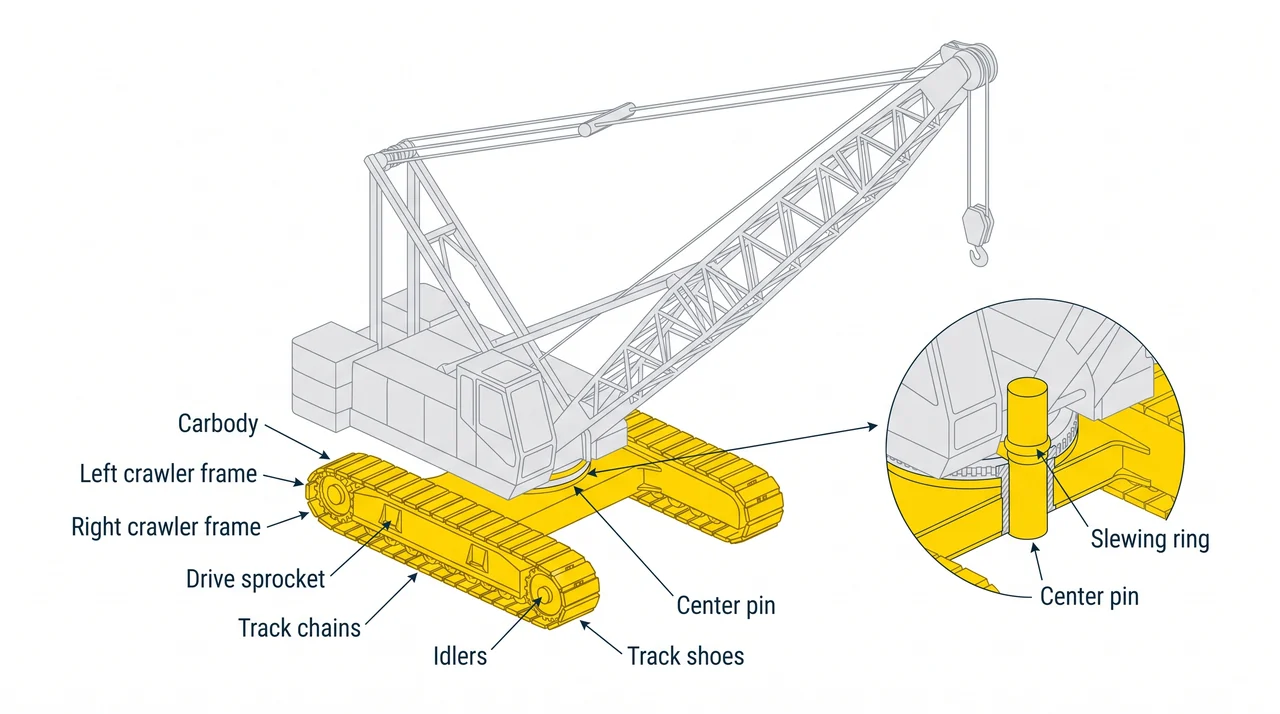
Lower works: carbody, crawlers, and the center pin
Everything below the slewing ring is the lower works. The carbody is its central chassis, and bolted to each side are the crawler frames, which carry the track chains, drive sprockets, idlers, and track shoes that contact the ground. That wide, continuous track footprint spreads the machine's weight over a large area, reducing ground pressure and providing stability on soft or uneven ground without outriggers — the defining advantage of a crawler over a rubber-tired crane.
The center pin, also called the king pin, passes through the slewing ring and physically connects the upper works to the lower works. Every load you pick travels through the boom, through the upperstructure, and into the ground through this pin. Any wear, cracking, or loose retention hardware at the center pin is an immediate removal-from-service finding.
Upper works: revolving frame, A-frame, and counterweight
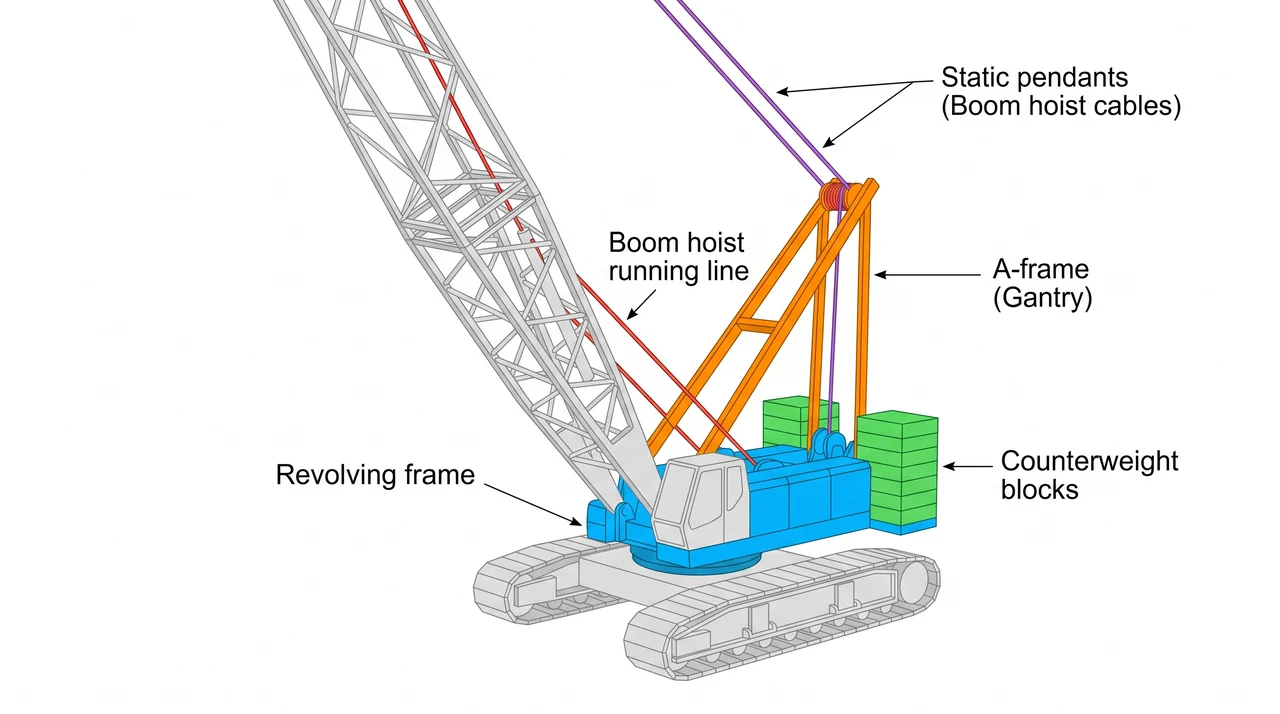
The upperstructure sits on top of the slewing ring and rotates 360 degrees around the center pin. The revolving frame is its backbone — a fabricated steel weldment that carries the cab, engine, hoist drums, and counterweight. Counterweight blocks hang off the rear of the frame to balance the boom and load out front. Without adequate counterweight the crane tips forward; with no load on the hook and too much counterweight it can tip back.
Rising from the rear of the revolving frame is the A-frame, also called the gantry or mast. Two separate wire rope systems work together here. The boom hoist line is a running rope reeved through the A-frame that actually raises and lowers the boom angle. The pendants — sometimes called boom hoist cables — are static structural wire ropes that connect the boom top to the A-frame and carry the tension load while the boom is working. Because pendants are always under tension, broken wires, kinks, or corrosion in a pendant are serious findings that require the crane to come out of service.
Lattice boom: butt, inserts, and head section
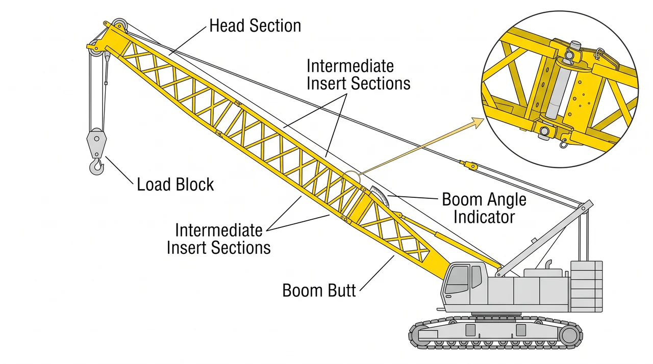
The boom assembles from pinned sections. The boom butt pins directly to the boom foot pivot on the revolving frame. Intermediate sections — standard and half-length inserts — are added above the butt to reach the desired working height. The boom top, or head section, sits at the crown and carries the load line sheaves, the boom hoist line sheaves, and the pendant attachment point. This modular design lets you configure boom length for the job, but every connection between sections is a potential failure site — pin condition, retaining hardware, and weld integrity at the chord members all require inspection.
Suspended from the load line is the load block — a multi-sheave bottom block with a hook — that actually connects to the load. The boom angle indicator, mounted where the operator can read it, shows the boom's angle relative to horizontal. Boom angle directly determines load radius, and load radius is what the operator uses to look up rated capacity on the load chart. Never position the boom without knowing both the angle and the resulting radius.
Friction winch system: clutch, brake, and drums
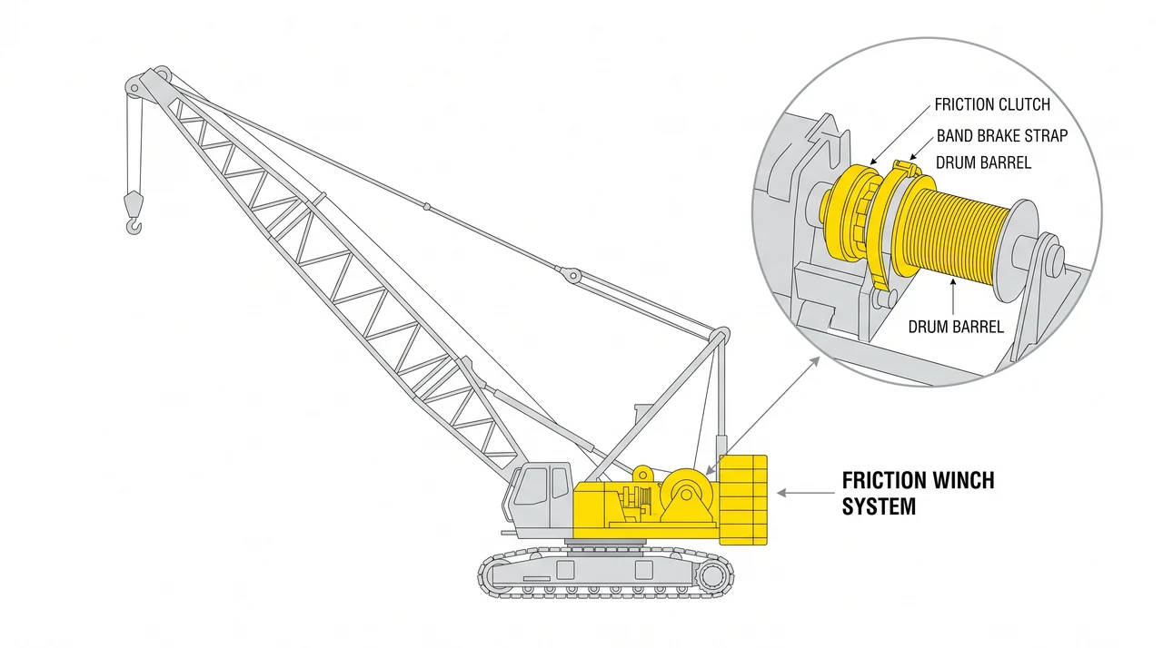
The defining feature of a 1A machine is the friction winch drum. Unlike a hydraulic hoist, a friction drum uses two separate mechanical controls: the friction clutch and the band brake. The clutch connects the drum to the engine drive — engage it and the drum winds in, raising the load. The band brake is an independent strap of brake material that wraps the drum; when applied, it grips the drum to slow or stop rotation. To lower a load, you release the clutch and modulate the band brake to control descent rate. Managing both controls simultaneously is the core skill that sets 1A operators apart. If you release the brake while the clutch is also out, the load freefalls — which is why worn brake lining is an immediate out-of-service condition.
Most lattice-boom crawlers have two drums: the main hoist for the primary load line and the auxiliary hoist, or whip line, for lighter secondary picks. Both require inspection before each shift.
Key Takeaways
- •The carbody and crawlers spread machine weight over a wide footprint, giving crawlers a stability advantage over rubber-tired cranes on soft ground.
- •The center pin connects upper and lower works and carries every load the crane handles — inspect it for wear, cracking, and loose retention hardware.
- •The boom hoist line is the running rope that moves the boom; pendants are the static structural wire ropes that carry tension while the boom is working — broken wires or kinks in either are removal-from-service findings.
- •On a friction winch, the clutch raises the load and the band brake controls lowering — the operator manages both independently, and worn brake lining means tag-out.
- •A lattice boom assembles from pinned sections (butt, inserts, head); the head section carries sheaves for both the load line and boom hoist line.
- •Boom angle determines load radius, and load radius drives the rated capacity look-up on the load chart — know both before every pick.