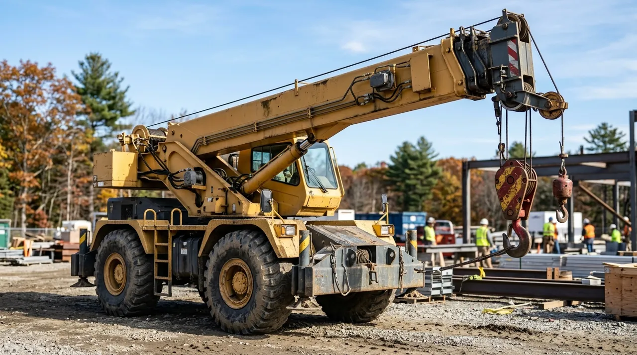
Before you can safely operate a telescoping-boom crane, you need a mental picture of how the machine is built. Every load-chart number, every inspection item, and every safety rule on the 1B exam traces back to an understanding of the physical machine. This lesson walks you through the crane from the ground up — carrier to hook block — so the components make sense before you start drilling capacity rules.
Carrier and upperworks: the machine in two halves
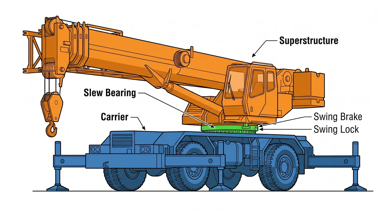
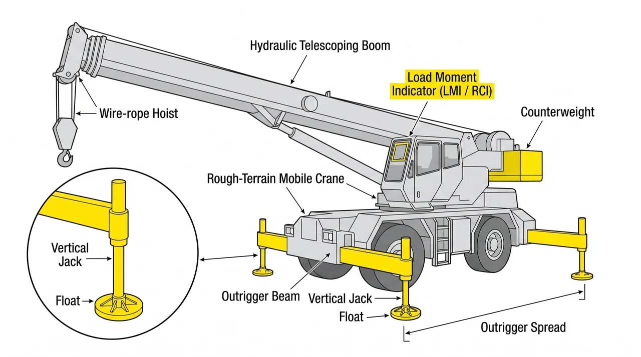
A telescoping-boom crane is built in two distinct assemblies. The lower half is the carrier — the truck chassis with its engine, axles, drive train, steering, and outrigger beams. It gets the crane to the site and provides the base everything else stands on.
The upper half is the superstructure: boom, hoist drum, operator cab, and counterweight. The superstructure sits on a slew bearing — a large ring gear — that lets it rotate 360 degrees independently of the carrier. The swing system includes a drive motor, a swing brake for controlled rotation, and a swing lock that must be engaged when the machine travels and released before lifting. The load chart gives separate rated capacities depending on whether the crane is on outriggers (tires off the ground, carrier locked down) or on rubber, because tire flex and shifting ground reduce the stability margin that the chart assumes.
The telescoping boom and its reach
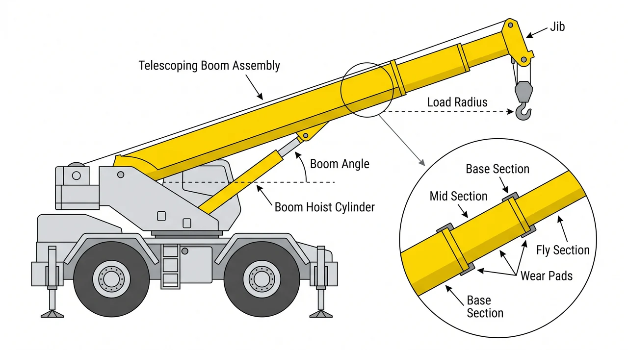
Unlike a lattice crane built from pinned sections, a telescoping boom extends hydraulically. The outermost tube is the base section; inner mid and fly sections slide outward on wear pads when the extend cylinder pushes them out. Wear pads carry each inner section against the outer one and must be inspected — worn pads allow the sections to bind and shift.
A separate component, the boom hoist cylinder, raises and lowers the entire boom to set the boom angle. Boom angle combined with boom length determines the load radius — the horizontal distance from the center of the slew bearing to the center of the suspended load. Load radius is the primary variable you look up on the load chart, so you must know your angle and your extension before any lift. When additional reach is needed, a jib pins to the boom head; it is rated separately and always at lower capacities because it moves the load further from center.
Wire rope, reeving, and the hook block
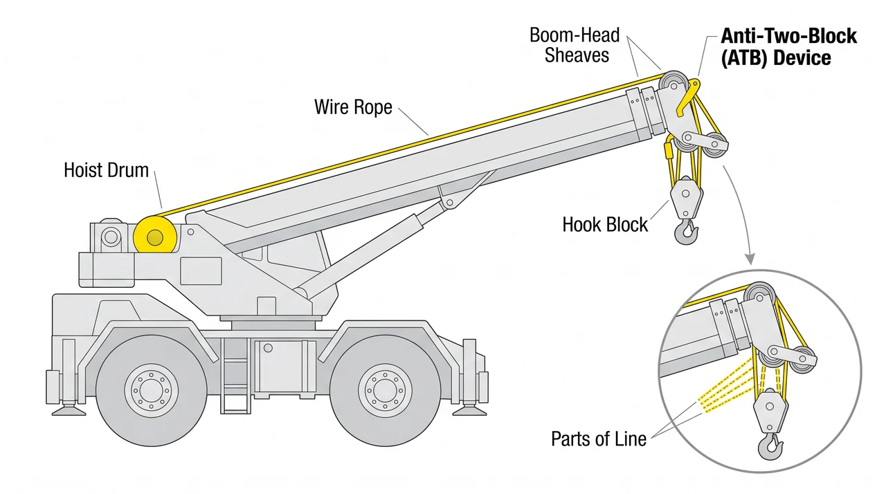
The wire-rope hoist line is what makes this crane a 1B machine. The hoist drum on the superstructure spools the rope through sheaves at the boom head and down to the hook block. Reeving is the arrangement of rope parts between the boom-head sheaves and the block's sheaves. Adding parts of line multiplies mechanical advantage, allowing the crane to lift heavier loads with the same drum pull — but at slower hook speed. Know your reeving because load charts may specify a minimum number of parts for certain capacity ranges.
The anti-two-block device (ATB) cuts hoist power before the hook block can contact the boom-head sheaves. Two-blocking — the block jamming into the boom head — puts the full hoist force directly into the rope with no release path and causes catastrophic failure. The ATB is a required safety device on 1B equipment.
Outriggers, counterweight, and load moment monitoring
Stability depends on outriggers and counterweight working together. Outrigger beams extend from the carrier sides; vertical jacks at the ends lift the carrier off the tires and transfer load through floats into pads or cribbing on the ground. Outrigger spread — fully extended, mid, or retracted — determines which column of the load chart applies. Using a capacity from the wrong column is a critical error.
The counterweight, mounted at the rear of the superstructure, creates an opposing moment to the boom and load so the crane does not tip forward. It is rated for a specific configuration; a wrong counterweight setup invalidates the chart. The load moment indicator (LMI, also called an RCI — rated capacity indicator) reads the suspended load against the crane's rated capacity for the current setup and warns the operator as that limit is approached. The LMI supports the load chart — it does not replace it.
Key Takeaways
- •The crane is two assemblies: the carrier (chassis, outriggers) and the superstructure (boom, drum, cab, counterweight) connected by the slew bearing.
- •Boom angle and boom length together set the load radius, which is the primary input to the load chart — know both before any lift.
- •Reeving adds parts of line to increase lifting capacity at the cost of hook speed; match your reeving to chart requirements.
- •Outrigger position determines your load chart column — never use a capacity that does not match your actual outrigger setup.
- •The ATB prevents two-blocking by cutting hoist power; the LMI warns as the load approaches rated capacity — both are required on 1B equipment.