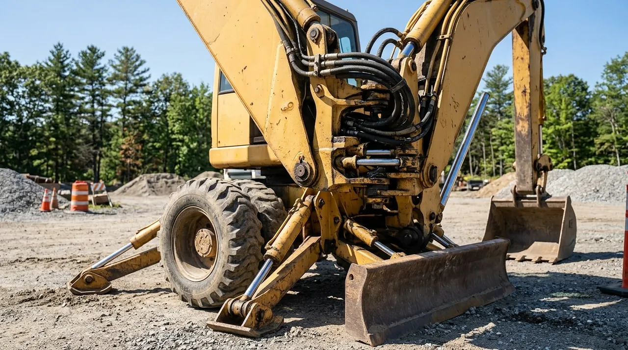
Before you can operate an excavator safely, you need to know what every part of it is called and what it does. That is not exam trivia — when a supervisor tells you to check the slew ring or a mechanic asks whether the stick cylinder is weeping, you need to know immediately what they mean and where to look. This session walks through the anatomy of a crawler excavator from the ground up, explaining how each assembly connects to the others and why each one matters on the job.
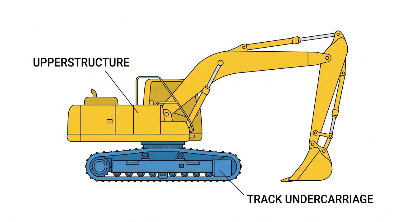
Two main assemblies: upperstructure and undercarriage
Every crawler excavator divides into two assemblies. The undercarriage sits on the ground and handles propulsion and stability. The upperstructure rotates freely on top of it and carries the cab, engine, hydraulics, front attachment, and counterweight. The connection between them is the slew ring — a large precision bearing bolted between the two — and that single interface is what makes the excavator so versatile.
Understanding the split tells you where to look when something goes wrong. A problem in the undercarriage affects travel and stability. A problem in the upperstructure typically affects swing, lifting capacity, or control.
The front attachment: boom, stick, and bucket
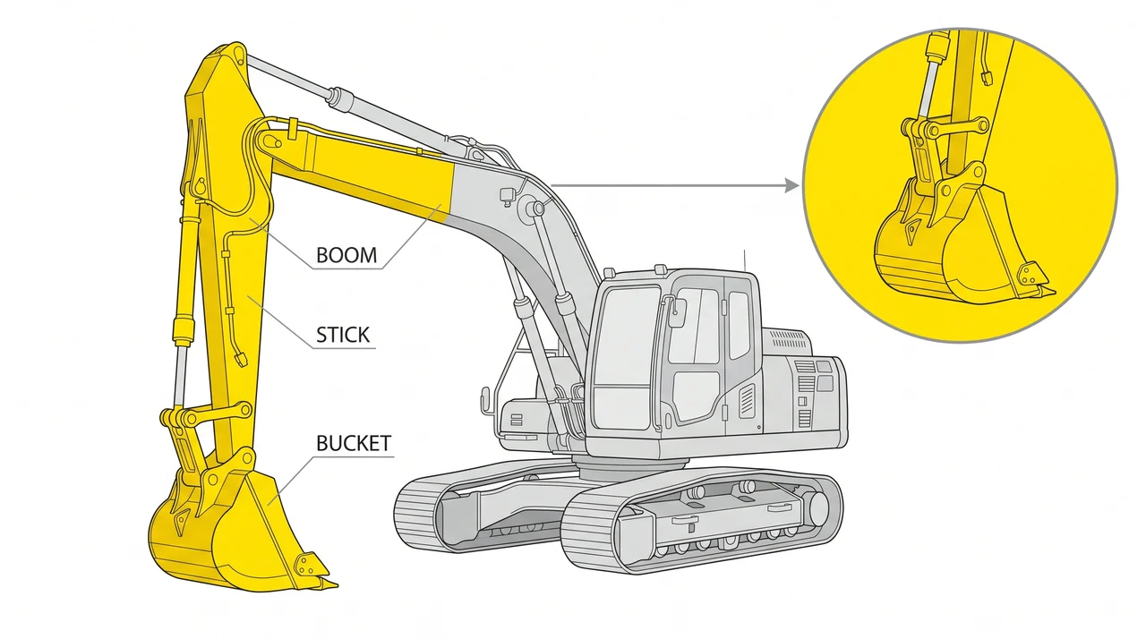
The working end of the machine has three articulating members, each driven by its own hydraulic cylinder. The boom is the large arm pinned to the upperstructure; the boom cylinder raises and lowers it, setting overall reach and cut depth. The stick — also called the dipper arm — pins to the end of the boom and extends reach while controlling how the bucket enters the material. The bucket at the end of the stick does the actual digging through its cutting edge, teeth, and side cutters. Side cutters are the wear plates along each cheek of the bucket that protect it when working in tight cuts against walls or forms.
The bucket connects to the stick through the mounting ears, the steel lugs that accept the stick pin and linkage pin. Cracks at the mounting ears are a removal-from-service condition because a failed ear can drop the bucket under load. Quick couplers allow the bucket to be swapped for thumbs, augers, compactors, or hydraulic hammers — always verify the coupler is fully latched before resuming work.
Slew ring, slew motor, and counterweight
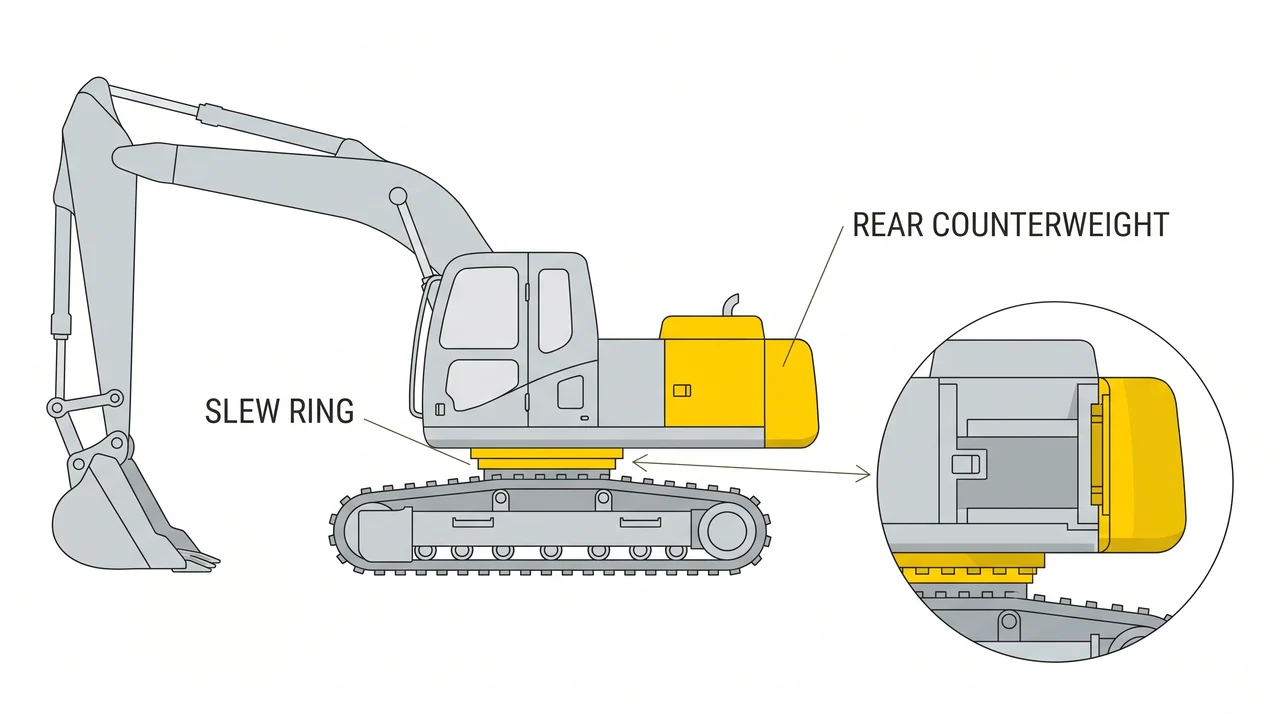
The slew ring bearing allows the upperstructure to spin a full 360 degrees independently of the tracks. The slew motor — a hydraulic motor inside the upperstructure — drives the ring gear on the slew bearing to produce swing. Because the slew ring carries the entire weight of the upperstructure and its loads, it is one of the highest-stress components on the machine. Grinding noise or jerky swing during start-up is an early indicator of bearing wear.
Opposite the front attachment, the counterweight is a cast iron block whose job is to balance the loads created when the boom is extended with a full bucket. Never operate an excavator with a missing or wrong-size counterweight — the machine can tip forward under load.
The undercarriage: tracks, rollers, idlers, and tension
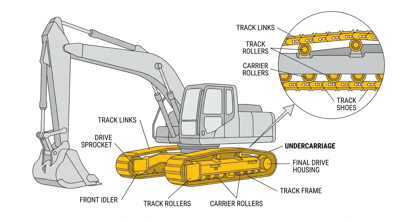
The track frame holds the drive sprockets at the rear, idlers at the front, and upper and lower rollers in between. The continuous track links run over all of them. Each side has its own hydraulic travel motor, and independent control of the two motors is what lets the machine steer or spin in place.
Track tension is a maintenance checkpoint you own as the operator. Tracks that are too loose can climb off the sprocket and derail. Tracks that are too tight accelerate wear on the rollers, idler, and links. Check and adjust tension every shift through the grease fitting on the tensioning cylinder per the manufacturer's specification.
The cab: protection, controls, and visibility
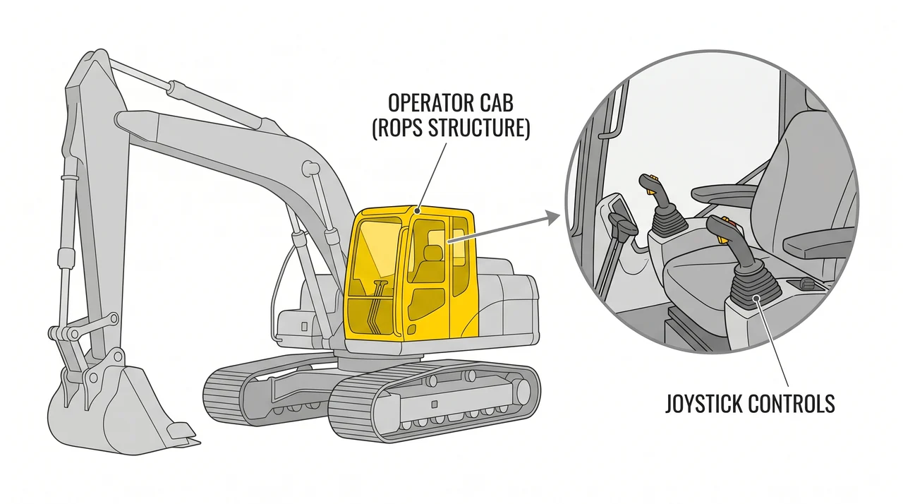
The cab is your work environment for the entire shift, but it is also a structural safety system. Excavator cabs are built to ROPS (Roll-Over Protective Structure) and FOPS (Falling Object Protective Structure) standards. ROPS protects the operator if the machine tips; FOPS — typically a heavy steel mesh or plate overhead guard — protects against material falling from above, which is a real hazard when working in trenches or near unstable slopes. Never remove or modify ROPS/FOPS guards.
Inside, the seat adjusts to keep you in proper reach of the controls without straining. Joysticks control boom, stick, bucket, and swing; foot pedals or levers control travel. Before starting work, walk around the machine to identify blind spots — most crawler excavators have limited rear visibility because the counterweight fills that space. Establishing swing and travel paths before digging reduces the risk of collisions with workers, utilities, or adjacent equipment.
Key Takeaways
- •A crawler excavator divides into two assemblies — the rotating upperstructure and the ground-engaging undercarriage — joined by the slew ring bearing.
- •The front attachment has three members (boom, stick, bucket), each moved by its own hydraulic cylinder; cracked bucket mounting ears are a removal-from-service condition.
- •The slew ring and slew motor enable 360-degree swing; grinding noise or jerky swing signals bearing wear.
- •Track tension must be checked every shift — too loose risks derailment, too tight causes premature wear.
- •The counterweight balances front-attachment loads; never operate with a missing or incorrect counterweight.
- •The cab must have intact ROPS and FOPS guards; establish swing and travel paths before digging to manage blind spots around the counterweight.