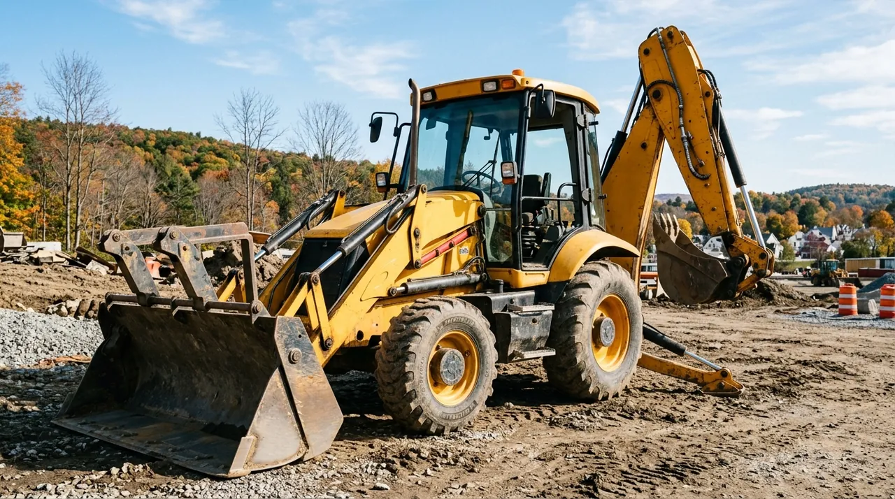
A backhoe loader is two machines built onto one frame. The front does loader work — scooping, carrying, dumping. The rear does excavating work — trenching, grading, breaking hard material. Operating both ends safely requires a clear picture of each major assembly, how the hydraulics tie them together, and what keeps the machine stable when you are working at either end. This lesson walks through the key components from the tractor base outward so the machine makes structural sense before you ever climb into the seat.
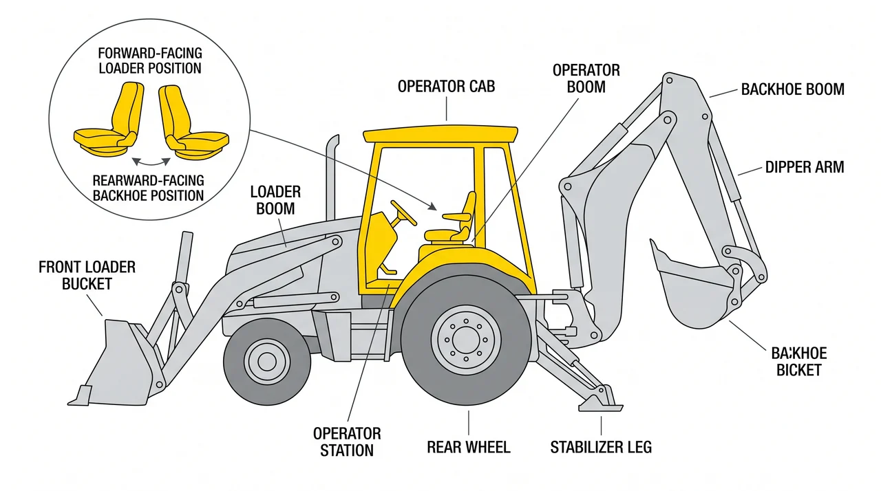
The tractor base and seat-reversal station
The wheeled chassis is the structural core. It carries the engine, transmission, axles, and operator station — everything that makes the backhoe loader self-propelled. The engine also drives the hydraulic pump that powers every cylinder on both ends, so an engine problem shuts down the whole machine.
The operator station sits between the two working ends, which creates a defining design feature: the seat must face either direction. When doing loader work you face forward. When you shift to backhoe work the seat swivels roughly 180 degrees to face the rear, and a separate set of controls becomes active for boom, dipper, bucket, and swing. Mixing up which controls are active in which position causes dangerous unintended movements in the field.
The front loader end
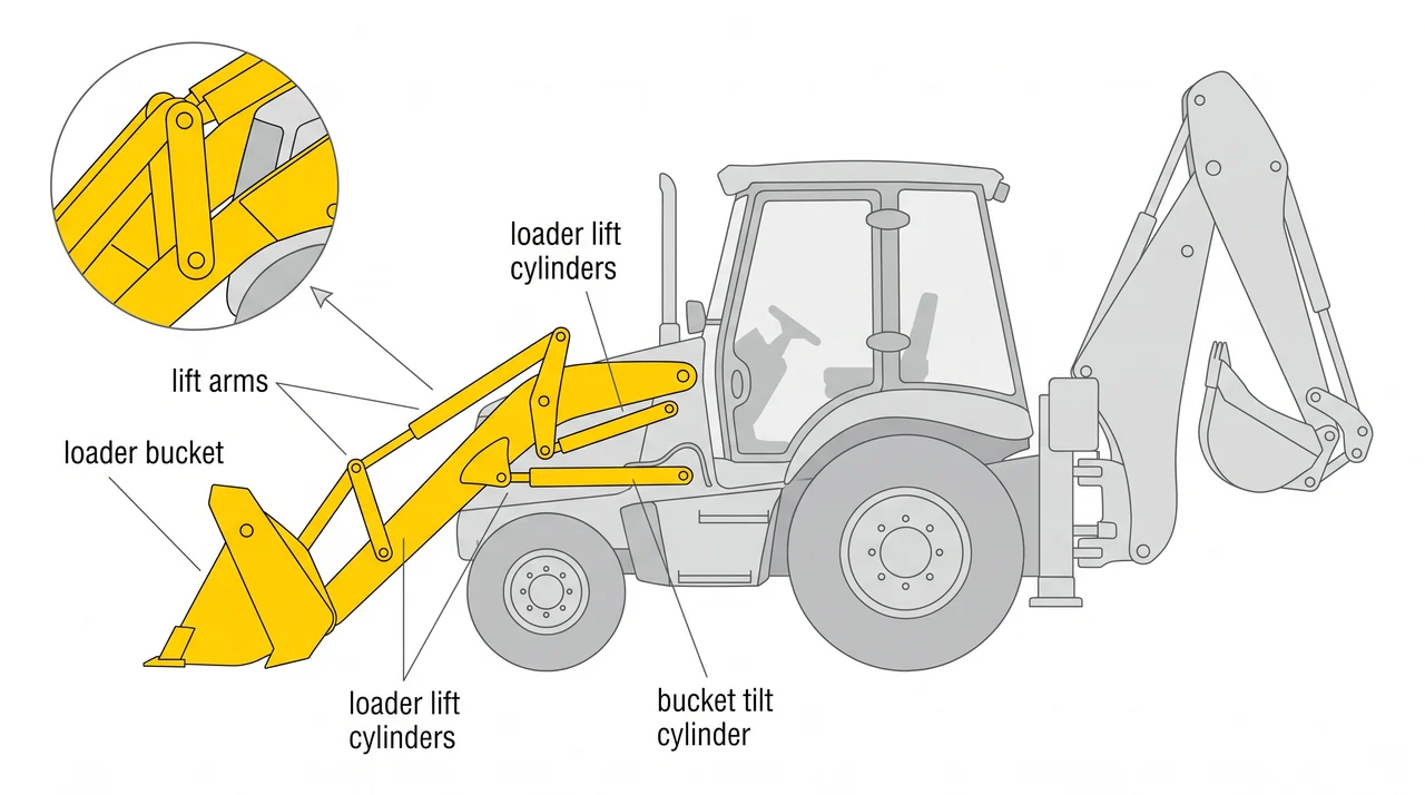
The loader end consists of two lift arms pinned to the front frame, a bucket mounted on those arms, and hydraulic cylinders that control lift and bucket tilt. Most machines use a parallel-linkage geometry so the bucket stays at a roughly constant angle as it rises — useful when carrying a full load. A return-to-dig function automatically levels the bucket when you lower the arms, reducing fatigue over a long day of repetitive cycles.
The rear backhoe: boom, dipper, swing tower, and bucket
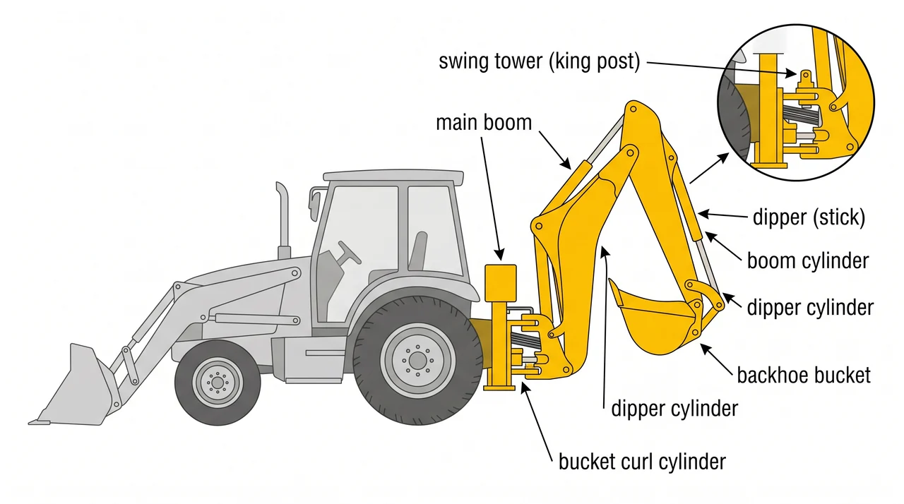
The backhoe end handles all excavating. The main boom is pinned to a swing tower, also called a king post, at the rear of the tractor frame. The swing tower lets the entire backhoe assembly pivot left and right within a limited arc — enough to dig on one side and place spoil on the other without repositioning the whole machine.
Extending from the boom is the dipper, or stick, which controls reach and depth. The backhoe bucket is pinned to the end of the dipper and curled or dumped by a third hydraulic cylinder. Boom angle, dipper extension, and bucket curl together determine exactly where the cutting edge works at any moment — reading and coordinating those three variables is the core skill of backhoe operation. Note that control patterns vary by machine: confirm whether the machine uses ISO or backhoe-style pattern before you start.
Stabilizers, the ROPS, and the transport position
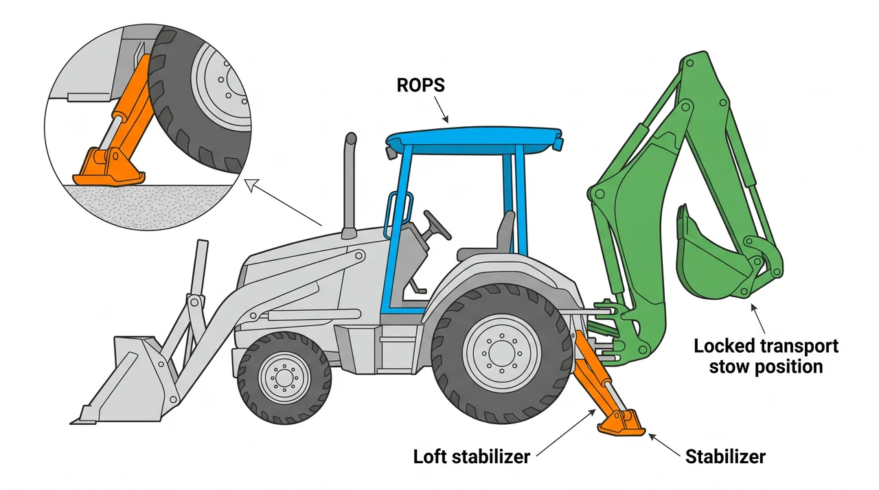
Before any backhoe work begins, both stabilizers must be fully lowered until the rear tires lift clear of the ground. This transfers digging reaction forces through the pads instead of the tires and prevents the machine from tipping or shifting under load. Operating the backhoe with stabilizers not fully deployed is one of the most common causes of tip-over incidents on these machines.
The cab or canopy provides ROPS and FOPS protection, but that protection only works if you are wearing your seat belt. The two systems are designed together — a ROPS creates a survival zone, and the seat belt keeps you inside it.
For travel, stow and lock the backhoe assembly — boom raised, dipper tucked, bucket curled — and fully retract both stabilizers. A machine moving with the backhoe swinging loose or stabilizers dragging is a hazard to anyone nearby.
Counterbalance, hydraulic system, and attachments
The backhoe loader is engineered with a counterbalance relationship between its two ends. When you are digging with the rear backhoe, the weight of the front loader bucket and arms acts as a counterweight that helps resist tipping forward. Conversely, the deployed stabilizers at the rear anchor the machine against the backward pull of a loaded boom. Neither end is incidental — each contributes to machine stability during the work of the other.
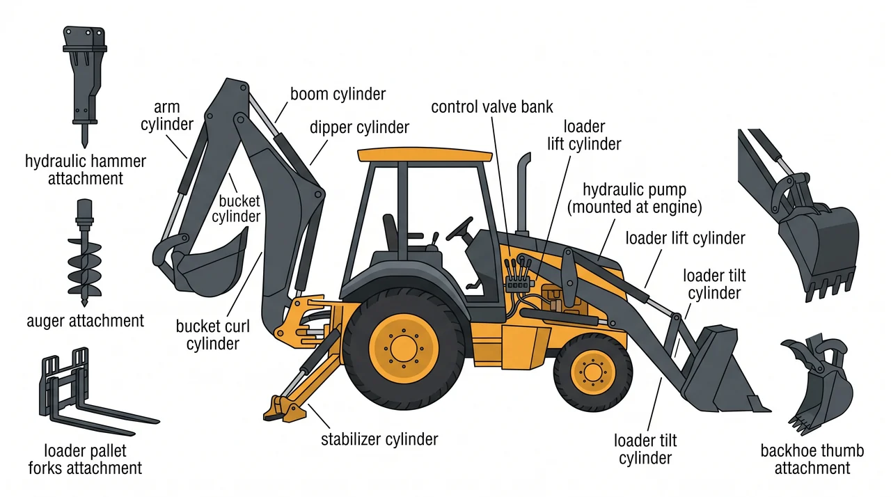
A single hydraulic system, driven by the engine, powers every cylinder on the machine: loader lift, loader tilt, boom raise, dipper extend, bucket curl, swing, and stabilizer deployment. The pump delivers flow to control valves that direct it wherever the operator calls for movement. Because all circuits share the same pump and fluid, simultaneous demands split available flow and can slow movements — understanding this helps you sequence inputs smoothly rather than fighting the system.
Both the loader and backhoe ends can accept manufacturer-approved attachments beyond their standard buckets. Common backhoe-end attachments include hydraulic hammers for breaking concrete or rock, augers for drilling holes, and thumbs for grasping irregular material. The loader end can accept pallet forks. Only manufacturer-approved attachments should be installed; improvised or non-approved tools can overload the hydraulic circuit, alter the machine's weight distribution, and create tip-over or attachment-failure hazards.
Key Takeaways
- •Both working ends — front loader and rear backhoe — are powered by one hydraulic system driven off the tractor engine.
- •The seat-reversal station switches between loader mode and backhoe mode; confirm which controls are active before operating.
- •The swing tower (king post) lets the backhoe slew left and right; boom angle, dipper extension, and bucket curl together position the cutting edge.
- •Both stabilizers must be fully deployed and the rear tires lifted before backhoe work begins — stabilizers up equals tip-over risk.
- •For travel, stow and lock the backhoe assembly and retract both stabilizers before moving the machine.
- •The loader end and deployed rear stabilizers form a counterbalance system that resists tipping during backhoe digging.
- •Only manufacturer-approved attachments — such as hydraulic hammers, augers, thumbs, and pallet forks — may be installed; non-approved tools create tip-over and failure risks.