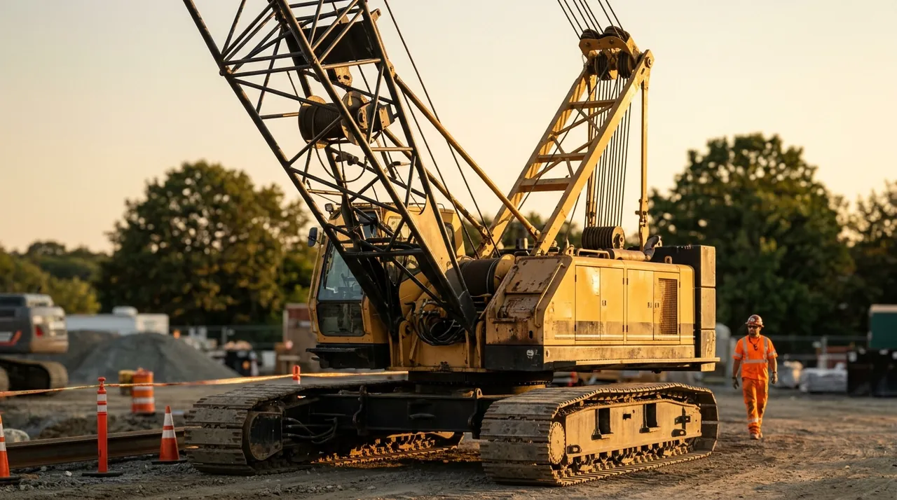
Wire rope and rigging hardware are the physical link between the crane and the load. The 1A exam treats this topic as a core competency because failed rope or improper rigging is a leading cause of dropped loads. This session covers how wire rope is built and why construction is matched to application, the OSHA criteria that require removal from service, how reeving creates mechanical advantage, and how to select the hardware that connects rope to load.
Wire rope construction and application
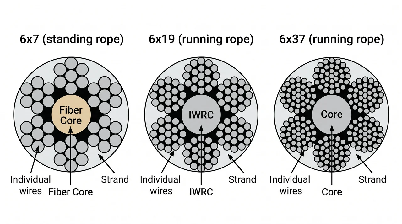
Wire rope is built in layers: individual wires twisted into strands, strands laid around a core. The core is either a fiber core, which provides flexibility and cushioning, or an independent wire rope core (IWRC), which adds strength and resistance to crushing under load.
The strand and wire count determines what the rope is suited for. A 6x19 or 6x37 construction has many small wires that bend easily, making it the right choice for running rope — the hoist line and boom hoist line that move constantly through sheaves. A 6x7 construction has fewer, heavier wires that resist abrasion but tolerate less bending, which is why it is standard for standing rope such as pendants. Rotation-resistant rope is a distinct category for single-part hoist lines where an ordinary rope's tendency to untwist would spin the load. Using the wrong construction in the wrong role accelerates wear and creates hazards that are not immediately visible.
Inspection and OSHA removal-from-service criteria
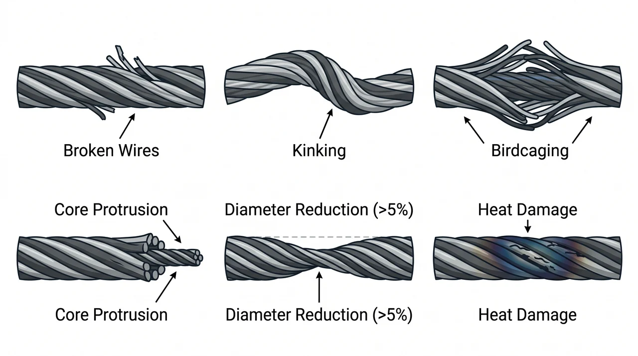
OSHA 1926.1413 sets the minimum criteria for removing running rope from service: six randomly distributed broken wires in one lay length, or three broken wires in a single strand in one lay. Rotation-resistant rope has tighter thresholds — two broken wires in six rope diameters, or four in thirty — because this construction loses strength more abruptly. Diameter reduction is a separate trigger: if a rope has worn more than five percent from its nominal diameter it must come out regardless of wire count.
Certain conditions require immediate removal no matter how few broken wires are visible: kinking, birdcaging, core protrusion, prior contact with an energized power line, heat damage, and a broken strand. A rope that touched a live line must be pulled even if it looks undamaged — electrical current damages internal wires in ways the eye cannot detect. These are no-exception removal conditions. The exam will test them directly.
Reeving, fleet angle, and drum requirements
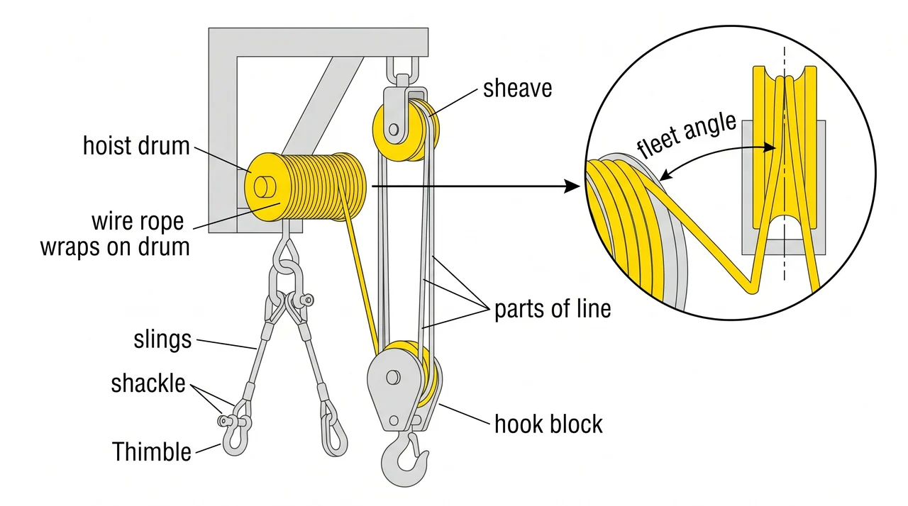
Reeving is the arrangement of rope through a sheave system to create mechanical advantage. More parts of line increases lift capacity because the load is distributed across multiple rope segments, but the hook travels more slowly for the same drum rotation. Knowing this lets you configure the crane correctly before the lift.
Fleet angle is the angle between the rope and the centerline of the sheave groove. Too steep an angle causes the rope to ride across the groove face rather than centered in it, accelerating wear on both rope and sheave. The maximum fleet angle is 1.5 degrees on a smooth drum and 2 degrees on a grooved drum. OSHA 1926.1417 also requires that at least two full wraps remain on the drum at maximum hook lowering so the rope stays anchored at its termination.
Rigging hardware and hitch configurations
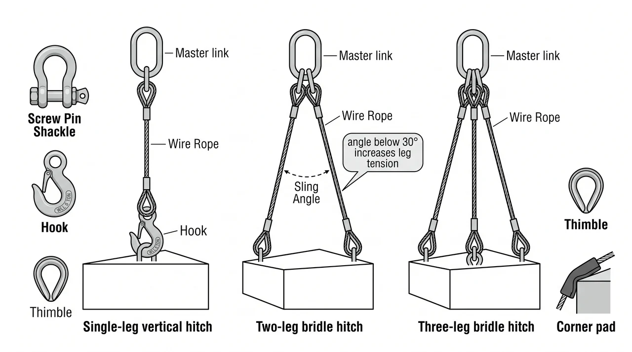
All rigging hardware — shackles, hooks, and rings — must carry a stamped or forged Working Load Limit (WLL). Never use unmarked hardware for a lift. If you cannot read the WLL, the piece is removed from the rigging, period.
Wire rope slings can be configured as a single-leg vertical hitch, a two-leg bridle, or a three-leg bridle. Sling angle has a significant effect on capacity: as the angle between each sling leg and the vertical decreases, tension in each leg increases. Below 30 degrees the force in each leg can exceed the weight of the load itself, which means the effective Working Load Limit of the sling drops dramatically — a sling rated for a given load in a vertical hitch cannot carry that same load in a shallow-angle bridle. Rigging plans specify minimum sling angles for this reason. Corner pads protect slings from sharp load edges, which concentrate stress on a small section of wire and can sever individual wires that the full sling would otherwise handle safely.
Key Takeaways
- •Wire rope construction is matched to application: 6x19 or 6x37 for running rope, 6x7 for standing rope, rotation-resistant for single-part hoist lines.
- •OSHA 1926.1413 removal criteria for running rope: 6 randomly distributed broken wires in one lay, or 3 in one strand; also remove for more than 5% diameter reduction.
- •Mandatory removal regardless of wire count: kinking, birdcaging, core protrusion, power line contact, heat damage, or a broken strand.
- •More parts of line increases lift capacity but reduces hook speed; fleet angle must stay within limit (1.5 degrees smooth drum, 2 degrees grooved) to prevent accelerated wear.
- •All rigging hardware must show a legible WLL; sling angles below 30 degrees dramatically increase leg tension and can exceed the weight of the load.