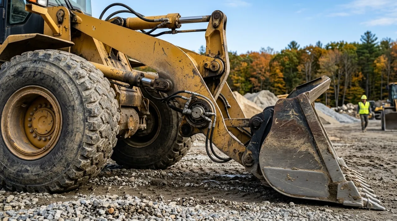
Before you can operate a wheel loader safely, you need to understand how its parts connect, how each system does its job, and where the design creates hazards you have to manage every time you climb in. The Massachusetts 2C exam tests that understanding directly. This lesson walks you through the major structures and systems so the machine makes sense to you as an integrated piece of equipment, not just a list of part names.
Frames, articulation, and why steering affects stability
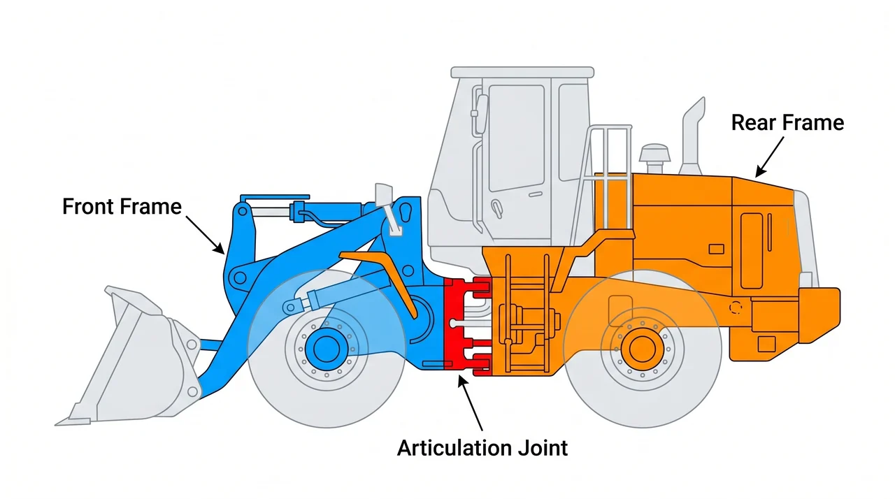
A wheel loader is built on two separate frames joined at a center pivot called the articulation joint. The front frame carries the lift arms, bucket, and front axle. The rear frame holds the engine, transmission, rear axle, and counterweight. When you steer, the two frames hinge at that center joint so the whole front half swings toward the direction of travel — the wheels do not turn independently the way a car's do.
This gives the loader a tight turning radius, but it creates a stability trade-off. When the frame is fully articulated — bent at a hard turn — the center of gravity shifts laterally toward the outside of the arc. Rated load capacity is lowest at full articulation for exactly that reason. The practical rule is straightforward: carry heavy loads with the frames aligned straight, and never make a sharp turn with a raised, loaded bucket.
Lift arms, linkage, and the bucket
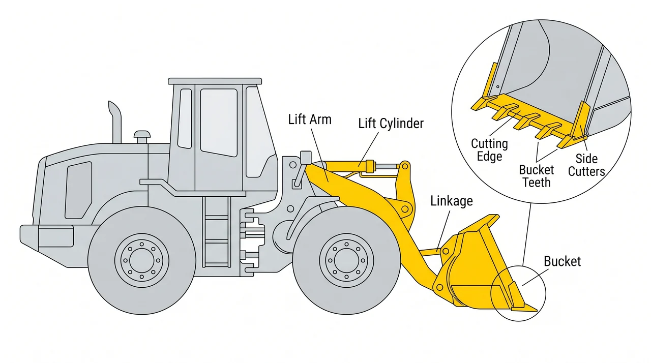
The lift arms connect the front frame to the bucket and are raised and lowered by hydraulic cylinders. The linkage geometry determines two things: breakout force — how hard the machine can dig into packed material — and whether the bucket angle stays level as the arms rise. A Z-bar linkage delivers high breakout force at ground level. A parallel-lift linkage holds the bucket at a nearly constant angle throughout the raise cycle, which helps when carrying loose material or pallet loads that would spill if the bucket tipped.
Buckets come in several types. A general-purpose bucket handles most earthmoving and aggregate work. A multi-purpose (four-in-one) bucket opens at the center to drop material like a clamshell, push, or carry. Rock buckets use heavier steel for abrasive material. Across all types, the cutting edge, teeth, and side cutters are wear items — inspect them before each shift and replace when worn.
Hydraulics and drivetrain
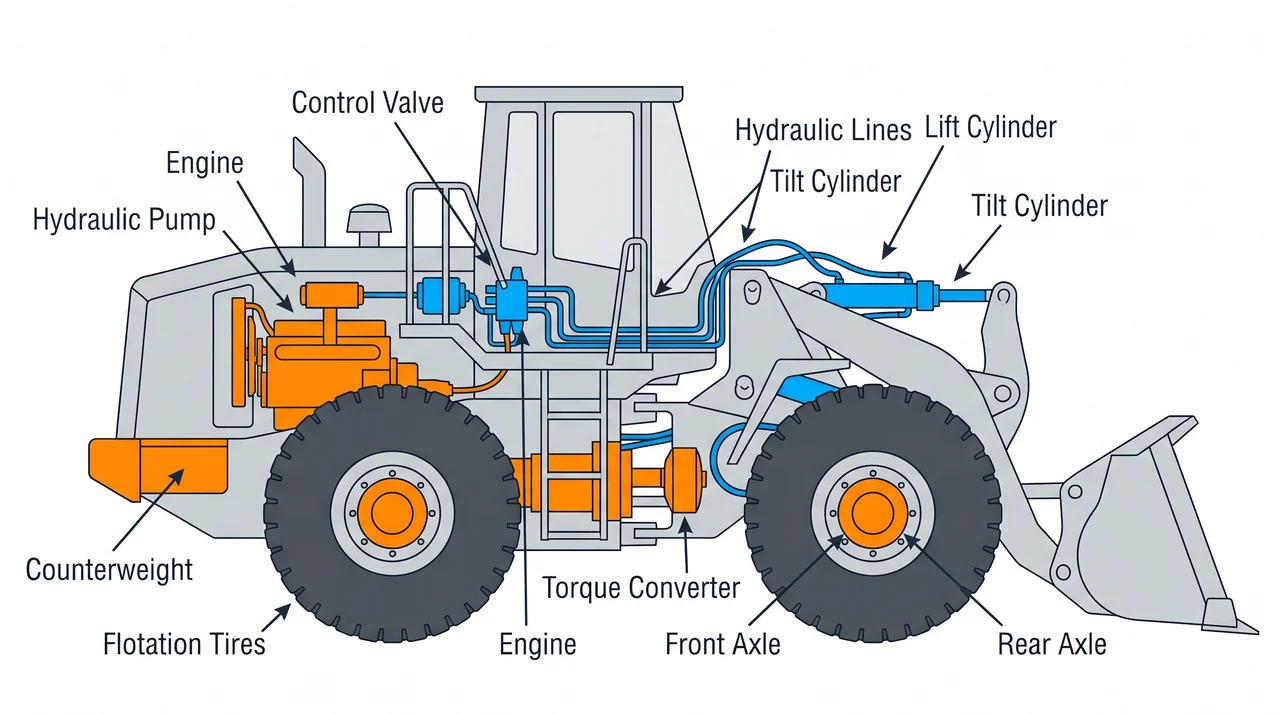
All working motion — raising the arms, curling the bucket — comes from hydraulics. A pump driven by the engine pushes fluid through a control valve to the lift and tilt cylinders. Filters keep contamination out of precision valve components. When you suspect a leak, the pressure inside a hydraulic line is high enough to inject fluid through skin, causing serious tissue damage. Check for leaks with a piece of cardboard — never a bare hand.
The drivetrain runs from the engine through a torque converter to the axles. The torque converter lets you hold the machine against resistance without stalling — essential when crowding into a pile. Large flotation tires distribute weight and provide traction on soft ground. At the rear, the engine mass and counterweight balance the loaded bucket at the front so the machine does not tip forward when you raise a full load.
Cab protection, operator restraint, and controls
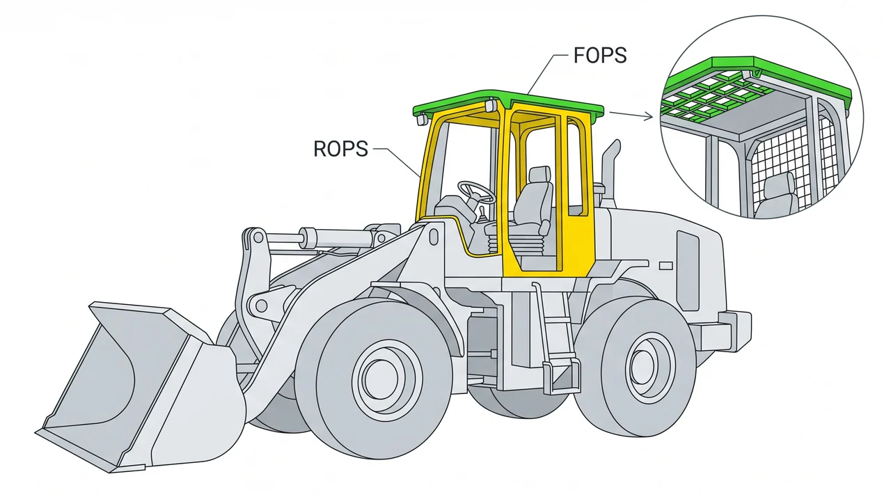
The cab has two protective structures for different hazards. The ROPS — Rollover Protective Structure — is the reinforced cage engineered to maintain a survival space if the machine tips over. The FOPS — Falling Object Protective Structure — is the overhead guard against debris from above, which is a real concern in quarry, demolition, and stockpile work. Both structures protect the cab space. They protect the operator only when the seat belt is fastened — if you are thrown from the seat during a rollover, the ROPS cannot help you.
The machine also needs functioning service brakes, a parking brake that holds on grade, a horn, a backup alarm, lights, and properly aimed mirrors. Attachments — pallet forks, grapples, and similar tools — connect through a front coupler, but only manufacturer-approved attachments for that specific machine may be used. An unapproved attachment is a modification that can void load ratings and introduce hazards the machine was never designed to handle.
Key Takeaways
- •A wheel loader steers by bending at the center articulation joint, not by turning its wheels; rated load capacity is lowest at full articulation because the center of gravity shifts outward.
- •Z-bar linkage maximizes breakout force at ground level; parallel-lift linkage keeps the bucket level throughout the raise cycle for better material retention.
- •Never check for a hydraulic leak with a bare hand — pressurized fluid can inject through skin and cause severe injury; use cardboard instead.
- •The rear engine mass and counterweight balance the front load; the ROPS protects the operator space during a rollover only when the seat belt is fastened.
- •Attachments must be manufacturer-approved for that specific machine — an unapproved coupler or attachment can void load ratings and create uncontrolled hazards.