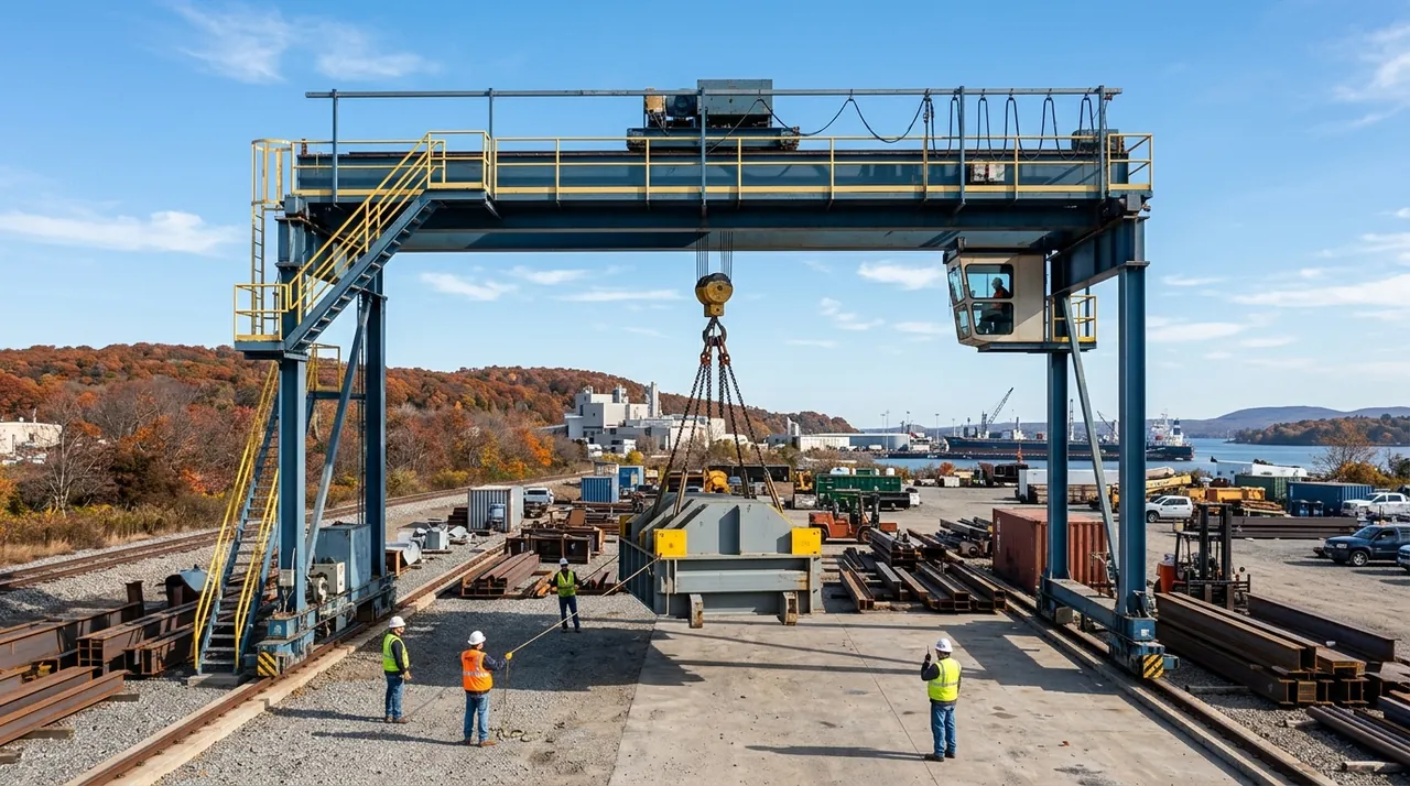
Not every lift happens with a large lattice-boom crane. A large portion of daily work in shops, yards, and marinas is handled by smaller dedicated equipment: jib cranes bolted to a wall or standing free on a single column, marine travel-lifts hauling boats out of the water, and tugger hoists pulling loads in tight quarters. Each type has its own operating logic, its own mechanical layout, and its own rules for what you can and cannot lift. Understanding how they work — and where they can fail — is what the exam will test and the job will demand.
Jib Cranes: Configurations and Capacity
A jib crane is built around one idea: a horizontal boom, called the jib, that rotates about a vertical axis. The mast can be free-standing — anchored to the floor on its own base — or wall-mounted, where the column or bracket is bolted into structural masonry or steel. Wall-bracket jibs are common in bays where floor space is tight, because the bracket transfers the load back into the building structure instead of requiring a separate foundation.
Because the jib sweeps an arc, the operator must always watch what is in that swing path. There is no separate load chart for a jib crane; the rated capacity is stamped on a plate attached to the structure. That plate is the governing document. Never estimate capacity from memory — find the plate, read the number, and stay under it. Some units also restrict where along the boom the trolley can travel, so verify that before loading.
Marine Travel-Lifts: Sling Placement and Balance
A marine travel-lift is a mobile gantry whose wide-set legs straddle a boat slip. Fabric slings hang from the crossbeams, drop into the water on either side of the hull, and are positioned under the boat before the lift raises the vessel clear. The slings cradle the hull rather than attaching to a hook point, which makes placement the critical skill.
One sling set goes near the bow, one near the stern, adjusted so the boat hangs level and the slings contact solid, supported hull sections — not through-hulls, keel bolts, or hollow sections that can crush under concentrated load. Spreader bars keep the slings at the correct width when hull shape requires it. Throughout the haul-out the operator relies on ground crew watching the hull, because the crew on deck can see what the cab operator cannot.
Tugger Hoists: Electric vs. Pneumatic
A tugger hoist is a powered drum that pays wire rope in and out to generate a pulling force. Tuggers are frequently used for horizontal pulls — dragging a load across a floor, tensioning a rigging line, or positioning heavy equipment — and can also pull vertically when the rigging geometry allows.
The main difference between drive types is the power source. An electric tugger uses an electric motor and suits general shop and construction work. A pneumatic tugger runs on compressed air and is the preferred choice wherever electricity poses a hazard: marine bilge spaces, spray booths, and other classified locations where a spark is unacceptable. Both types use mechanical brakes to hold the load when the control is released, and both require overload protection to prevent the drum and brake assembly from being loaded beyond their design limits.
Chain Hoists and Wire-Rope Hoists: How They Work and What to Inspect
A chain hoist lifts by pulling a load chain over a pocketed lift wheel. The chain engages the pockets positively, so a chain hoist holds any position reliably without the chain slipping. Inspect the load chain for twisted, kinked, cracked, or stretched links, and check the contact surfaces where the chain engages the wheel — wear there causes the chain to seat improperly and jump.
A wire-rope hoist uses a drum to wind wire rope that runs through sheaves to a hook block, providing higher capacities and faster speeds. Inspect wire rope for broken wires, kinks, bird-caging, corrosion, and worn sections. Check sheaves for groove wear and alignment. Both hoist types must have functioning brakes and overload protection. ASME B30.16 and B30.17 govern these units and establish the minimum standards for rated load markings, inspection intervals, and safe operation.
Key Takeaways
- •A jib crane's lifting limit is set by the stamped capacity plate on the crane — there is no separate load chart.
- •Marine travel-lift slings must contact solid hull sections fore and aft; spreader bars maintain correct sling width when the hull shape requires it.
- •Pneumatic tugger hoists are chosen over electric ones wherever a spark from an electric motor would be hazardous.
- •Chain hoists use a load chain over a pocketed lift wheel for positive hold; inspect for twisted, kinked, or worn links.
- •ASME B30.16 and B30.17 set the standards for overhead hoist rated load markings, brakes, overload protection, and inspection intervals.